
Ubiquiti EdgeRouter Lite Setup Part 3: VLAN Setup
Those who have followed along with parts 1 and 2 of this series should now have an ERL configuration with one WAN and one LAN interface and a zone-based firewall. Let’s take another look at our example network configuration diagram.
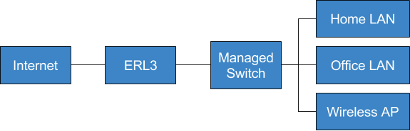
Rather than the single LAN we have now, this shows separate home and office LANs. It also shows a wireless AP which will supply wireless networks for both LANs.
One way to separate the home and office networks would be to put them on different interfaces of the ERL, e.g. the home LAN on eth1 and the office LAN on eth2. This would work but has a some disadvantages - reconfiguring the network might involve rewiring, and each network needs its own wireless AP.
A more flexible option is to use virtual LANs (VLANs). With VLANs the networking equipment provides a logical separation of networks which can easily be reconfigured in software. A single interconnect can carry traffic for multiple VLANs using 802.1q VLAN tagging, which allows deploying a single AP which serves wireless networks for both LANs or even multiple APs throughout the building all serving multiple wireless networks.
Using VLANs does require that at least some of your other networking equipment support VLANs. In a small network a single managed switch is sufficient, and wireless APs need to support defining multiple SSIDs with VLAN tagging.
In this post we’ll learn how to set up VLANs on the ERL. A VLAN deployment will also require configuring switches and wireless APs, but exactly how to do this is hardware-specific and thus will not be covered here.
Adding VLANs
A VLAN is created by adding a virtual interfaces or vif to one of the physical interfaces. For our network we’ll define three VLANs. Each VLAN will need its own pool of addresses to assign to clients. For this example we’ll use:
- VLAN 1: Management network. This is the network used for communication between the network hardware. Subnet: 192.168.101.0/24.
- VLAN 2: Home network. Subnet: 192.168.102.0/24.
- VLAN 3: Office network. Subnet: 192.168.103.0/24.
VLAN Configuration
We’ll configure the management LAN as an example. First we need to add the vif to eth2:
$ configure
# edit interfaces ethernet eth2
# set vif 1 description "Management VLAN"
# set vif 1 address 192.168.101.1/24
# top
Next, set up DHCP and DNS for this network.
# edit service dhcp-server shared-network-name mgmt
# set authoritative disable
# set subnet 192.168.101.0/24 default-router 192.168.101.1
# set subnet 192.168.101.0/24 dns-server 192.168.101.1
# set subnet 192.168.101.0/24 lease 86400
# set subnet 192.168.101.0/24 start 192.168.101.150 stop 192.168.101.254
# top
# set service dns forwarding listen-on eth2.1
Repeat this procedure for the home and office VLANs.
Firewall Rules
Firewall rules and zone policy also need to be defined for the management zone. I won’t cover this in detail here; refer to part 2 for guidance.
Deleting the Old Configuration
Once the VLAN configuration has been verified to be working with other networking equipment, much of the old configuration for the LAN is likely no longer needed. It should be safe to delete the IP address for eth2 and the DHCP settings, DNS settings, and zone policy for the old LAN network. Any firewall rulesets that are no longer used can also be deleted. Make sure that you delete only the rules for the eth2 interface itself and not for its VLANs. Also be sure that the firewall rules allow access to the router configuration from at least one of the VLANs, otherwise you may find yourself locked out!
Guest/IoT VLAN
Though this isn’t included in the example network we’re setting up, it’s definitely worth mentioning.
Setting up isolated wireless networks for guests and/or internet of things (IoT) devices is a really good idea. Guests could be bringing compromised devices into your network, and IoT devices are infamous for their poor security practices. Unless you have a specific reason that the device needs to be on the same network as your other machines (e.g. a wireless printer) it’s better to put them on an isolated network.
Using the information above it is strightforward to add one or more additional VLANs for these devices. Set up the vlan similarly to the one above, set up DHCP with an unused range of IPv4 addresses, add a new firewal zone for the network, and configure the firewall so that all trafic to and from the zone is dropped except for WAN traffic. Pro tip: If the default action for your zones is drop you don’t actually need to explicitly add rules to drop traffic between two zones.
Conclusion
That’s it for our brief overview of setting up VLANs on the ERL. In part 4 we’ll talk about deploying IPv6 on the ERL.
Comments